by Chinky420 » Mon Sep 21, 2009 9:21 pm
what you need:
2.75" mandrel bent aluminized piping (jc whitney has it in their 'exhaust' section)....make sure you get the piping that has a 180 degree bend.
a sawzall with a metal-cutting blade
a dremel
a file
a drill with metal bits
a filter (with a 2.75" outlet)
3x 2.75" couplers
an old MAF holder/housing (or you can cut up your OEM airbox, but that kinda limits you from going back to OEM)
what i did for my 3" custom intake is this:
i took my 180* piping and cut it into 3 sections....
three sections so that i can have a straight section from the throttle body towards the battery...the other two sections are going to have to be cut so that they fit/conform to fit through the fender under the fuse box.
got that?
1 section straight (from TB to battery-area)
2 sections (the curvy part and another curvy/straight part) to angle the tubing down into the fender
next thing i did was cut off the housing for the MAF with a dremel (and a hacksaw, and a number of other things)...then i filed/sanded it down so that it had a curved edge (since it's gonna be bonded to the side of the tube)
next thing i did was draw on the piping where to make the cut to place the MAF housing on the pipe (i.e. i traced an outline of the MAF housing with a sharpie so i knew where i had to cut the MAF hole).
then i drilled holes into the four corners of where the MAF will go, then 'connected the dots' with the sawzall, so that the center part came out (where the MAF goes into the pipe) <----this step was the most frustrating, as cutting/drilling through metal piping is difficult, and it is already an akward shape. with some persistance and cleverness, you should be able to do it.
****NOTE: make sure to make the hole a bit smaller than the tracing, as you traced the outside of the MAF housing, and the MAF sensor itself is smaller still****
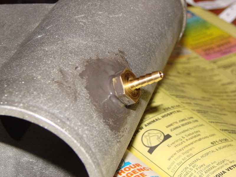
you're going to drill 3 holes for the vaccum lines...i forget the sizes (i think 1/8", 3/8", and 5/8" ?!?!? don't quote me on that part). what i did was get the hoses, and find appropriate sized thingies (yeah, i'm blanking on what they're called). basically, i have three little mini tubes sticking out throughout the big pipe, so that the vaccum lines can hook up to the intake. find a place for them that will reach the hoses, and/or find out whether or not you'll have to buy new hoses to reach.
JB weld these 'mini pipes' in place and JB weld the MAF housing onto the pipe (after test fitting, to make sure that MAF will go into pipe). fill in any holes that are around the MAF housing....leave to cure for a day or two
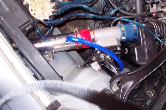
find 2.75" couplers that can connect the TB to the piping...then find another two couplers to connect the piping to the other peices (the ones that are going into the fender).
attach filter (actually, you might attach filter before fitting all the peices together)...and you should be done.
some notes: if you read carefully, you noticed i suggest for YOU to do 2.75" while I did 3".....this is for two reasons:
1- 3" piping messes with our MAF readings, which throws a CEL. this CEL will stay around until you either go back to OEM, use a 2.75" intake, or re-tune with an A/F unit (allegedly ..... i've never seen it personally, but i've heard that it's one solution to the problem)
2- 3" piping is too big to feed into the fender, unless you're a big fan of taking a hammer to your engine bay to make room. even if you can get it down there, there's no guarantee that you'll be able to angle the 3" piping forwards, and also have the coupler fit under there...it's actually kinda tight where you need the pipe to make the turn forward, blame it on the splash guard.
the original place i found the DIY was some one-off honda site. i can't find it at the moment.
one other note, since i didn't actually get mine to be a CAI, i didn't worry about finding a way to support the intake. currently, i have the pipe 'hanging off' (not actually hanging...but it's not 'secured'), and the filter is pointing downwards, and supporting the weight from the filter making contact with the engine bay.
not the best setup, but it works...the whole thing is actually really sturdy, and doesn't move at all...yes i have a CEL, no i haven't retuned. end result: car stays in a 'warm up loop' where it runs a bit rich for safety.
basically, it's some work, but it's doable. get creative and write up a tutorial (i never overcame my hurdles of feeding into the fender, or making a stable mounting system...so i never got around to doing a write up)
if you have any other questions lemme know, and i'll try and answer as best i can....