somebody have the springs from tein in a Solara 3.3
???
???

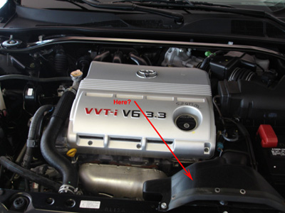
panic wrote:I'm looking for a cold air kit for my G2 3.3, but all the leads I track down described as "cold air" are simply aftermarket open sided filters at the end of a curved extension.
Is there a product out there?
Some of what is claimed and posted about intakes is complete rubbish. In general, there are a few things that may help:
1. new tube has larger radii and/or diameter than original plumbing - improves air volume
2. the tube (and the entire tract) must have a smooth interior wall - the flexible, conformable flex tubes are completely worth - the spiral or corrugated inner wall drastically reduces air-flow
3. new filter area is larger than the OEM - but not always an accurate comparo since not all filters flow the same per square inch of area.
4. a filter re-located to anywhere inside the engine compartment gets only pre-heated air from the engine. Under WOT the heat throw-off from the exhaust and hot air pulled through the radiator by the fan is huge.
5. pointing an external intake scoop forward does not produce enough "free supercharging" to make much difference, the wind pressure is only about 1.2% at 100 mph
6. even a K&N has to be big enough to work; example: a 3.3 peaking at 6,000 RPM needs about 47 square inches of filter to work (6" × 8" panel, etc.).
Formula: engine size in liters * RPM ÷ 418
3.3 × 6,000 = 19,800, ÷ 418 = 47.4 square inches
7. when you remove the original stuff, you get a bit more intake roar (sounds nice, though!), but I'm not sure if it cancels any Helmholtz benefits? Is the stock air box a resonator?
8. the biggest power boost you can get from changing the intake duct is cold air - the difference between 70° ambient from the exterior vs. 150° or more inside the bay is large. The duct from the entry need not be continuous diameter - it can end in a big box containing the filter, then another tube back to the TB.
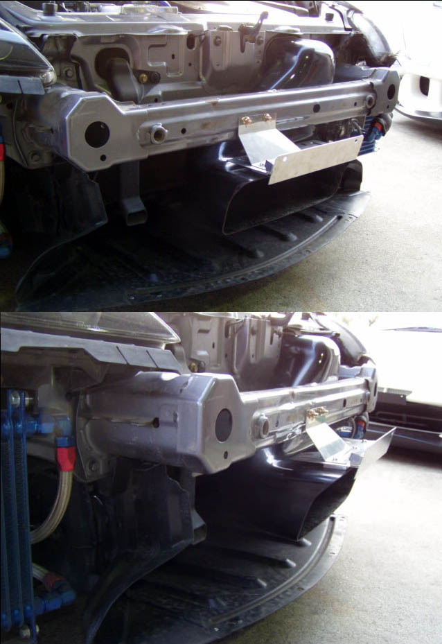
What I'm looking for is an intake that has a remote tube ending outside the engine bay in front of the bodywork (grill, under bumper, etc.). The better ones will have a water trap to prevent rain and road dirt from reaching the filter.
Thanks for any leads or links.

 .
.
panic wrote:Re: "(6) I'm lost (please explain what is the purpose of formula)"
That's just the K&N formula for minimum filter area, converted to liters.
In inches: Displacement × RPM × VE ÷ 25,500
(4) IMHO there's probably lower air temperature available in some underhood areas than others, depending on how air flows at speed.
A temp probe could be tie-wrapped in a few places to test this. At idle, traffic, etc. I'm sure underhood air exceeds 200° F because there's nowhere for hot air (radiator, block, exhaust) to go, but it probably flushes out at higher speed - but what area (if any) is swept down to ambient???
(5) I'm having a bit of argy at the SCTA/BNI site about this. I can't understand how increasing the inlet size (above actual inlet diameter) does not create more velocity which translates back to pressure when the X-area increases in the plenum.
The opinion offered is "the larger opening creates aero drag" - this is not only "unresponsive (common term at trials, means "you said something, but you didn't answer the question"), but irrelevant where the scoop is in "hidden" in the existing frontal area.
(7) For those not familiar, a volume in between the atmosphere and the carburetor (not a manifold plenum) can produce very small positive pressure at a tuned RPM. Quoting from my own booklet:
"Concept: ... improve performance by use of a tuned common air filter housing or “box”. This is especially useful where the tuned intake tract length has been selected to add power at or near the existing power peak. The engine should have between two and four cylinders for effective use (a V6 would have 2 boxes).
The principle involved is the “Helmholtz resonator”. Herman L. F. von Helmholtz (1821-1894) published “On the Sensations of Tone” in 1862, in which careful calculations allow incoming air to develop slight positive pressure (mild supercharging) through “flask resonance” (the behavior of sound and pressure inside a bottle) inside the air-box, and provide additional flow through the carburetors.
It is the size and shape of the box itself which provides the benefit. The interior volume of the box is a function of several factors, including the engine displacement, the number of cylinders, and the RPM at which the enhancement is to occur. The volume affects the tuned speed somewhat, but is secondary to air intake tube length."
I thought of an easy test to determine if the existing air box is intended to act as a Helmholtz device.
Add a "stuffer" to the air box (something clean and large like a cardboard box, or even a balloon) to reduce the volume by perhaps 1/2 to 2/3 (without obstructing any openings - use duct-tape). If the engine feels weaker in low to mid ranges it may have been from altered resonance characteristics.

panic wrote:"Is there an assumed VE"
100 is the default, but for an engine with VVT and tuned intake perhaps 105 is safer since a bit more is harmless if wrong.
(5) My argument was that the ram effect limit was based on the principle that the air inlet size was fixed, but I can't find any technical reason for this.
Yes, an 8" scoop on top of the hood will reduce the top speed (perhaps) more than any power it will add - but what if the entry is completely shrouded by the existing frontal area (area does not increase), and located where drag is already high (Cd not effected)?
There are Bonneville cars running upwards of 200 that have exponential horns projecting ahead of the bodywork for just this purpose, and the rules are very critical as to interpretation of "what is a radiator shell", etc. - so you know this works. Granatelli used projecting horns in the lamp sockets of his 1960 Chrysler 300F at Daytona.
(7) True, in fact by trashing any calculated length characteristics in the original inlet system a CAI etc. could be improving mass flow, and still reduce power. Except for the obvious space considerations, the SRI tube could be made of 2 telescoping sizes (ID #1 = OD #2), and a manual cable could be used to slide the length up and down under power like a trombone. If the tube is curved, 2 separate sliders could be used to keep the bulk down. Once the length is known (if actually within a range you can fit) a solenoid can move it triggered by a lead to some electronic event like the VVT to switch from low to high range.
 I've seen people take out foglamps to make ram air scoops...not that I'll do it to mine (light bulb turns on then back off due to $$$). Check what Volant has as add-on (scoop) to their air filter systems (in light grey):


