TLMNICK's Install Tutorial: Install your Own alarm/Starter
![]() by TLMNICK » Wed Apr 29, 2009 3:50 pm
by TLMNICK » Wed Apr 29, 2009 3:50 pm
READ THROUGH THIS ENTIRE TUTORIAL A COUPLE TIMES BEFORE YOU PHYSICALLY ATTEMPT ANYTHING, or before asking questions.
I keep coming across threads regarding alarm system installations, and it's always tough to help someone through it unless you're right there with them. So I decided to write this tutorial in the hopes of it being an effective tool/aid to those who are looking to undertake the daunting task of installing their own alarm/starter system.
Something to keep in mind: THIS TUTORIAL IS TO BE USED AS AN AID ONLY. SOME THINGS IN YOUR CAR MAY BE DIFFERENT, AND I AM NOT RESPONSIBLE FOR ANYONES MISTAKES. INSTALLING AN ALARM/STARTER IS NO EASY TASK FOR THE INEXPERIENCED. I do not recommend that anyone try this if you have no prior electrical experience. As an installer, I am using this to try and help. I can be reached through PM if anyone has any specific questions regarding the installation.
The install I'm about to walk you through was done on a 1999 TOYOTA CAMRY XLE AUTOMATIC. Although they are very similar to the gen1 solara, there will be slight differences....but for the most part, everything from this install can be applied directly to a gen1 solara. The system I installed was a Compustar Pro 2WFMAS.
So Let's Get Started.
1. The first thing you're gonna wanna do is prepare your system for install. Open the package and make sure everything is there. It makes for an easier install if you know exactly which wires you need to use on the alarm for any given vehicle. Typically you'll never use ALL the wires...so if you can eliminate the ones you know you wont need before you even get to the car, then it'll save you some trouble. Plus it'll make for a neater install. You'll know which wires to use based on whatever wiring diagram you're using as reference. I used this one:
http://64.85.6.121/diagrams/printpage.a ... 2&MakeID=2
You can see in the diagram, that you'll need the following wires:
12volt Constant - this is a wire that has power in it at all times regardless of the position of the key. It is what gives the alarm its power. (WHITE)
Ignition 1 - This is a wire that has power when the key is in the "on" position, and retains its power during cranking. (Black/yellow)
Ignition 2- This wire is the same as ignition 1, but these cars require that you power them BOTH up. Most remote starters will have another ignition output built in. (black/red).
Accessory - This is a wire that has power when the key is in the "ACC" , or "ON" position, but NOT the "crank" position. (Blue/red)
Starter - This wire only has power in it during crank. Its what sends the signal to the starter under the hood. (red)
Keysense - This is a wire that carries a ground when the key is in the ignition. This wire will be used to disarm the alarm system during remote starting. In doing this...the car will be able to remote start without the factory alarm going off. (blue/black)
Parking lights - This wire will carry a 12volt pulse when the parking lights are switched on. This wire will be used to flash the parking lights during arm/disarm, and remote start...it'll also flash the parking lights when the alarm is triggered. (green)
Power Lock - This wire has a ground pulse when the key is inserted in the passenger door, and turned to the "lock" position. It is used to lock all the doors, and arm the stock alarm. (darkblue/white)
Power Unlock - This wire has a ground pulse when the key is instered into the passenger door and turned to the "UNLOCK" position. It is used to unlock all the doors an to disarm the stock alarm. (darkblue)
Door trigger - This is a wire that has a ground pulse when any of the doors are opened. It is used to trigger the alarm system in the event that someone manages to open the door. (red/white)
Trunk trigger - This wire is used to trigger the alarm in the event that someone manages to open the trunk (red/yellow)
Brake Switch - This wire has a 12volt pulse when you put your foot on the brake pedal. It is used to shut the remote starter down in the event that someone gets into your car while its remote started. When they go to shift out of park...it'll shut down, and they wont get far. Its also used to cancel the remote starter if its no longer required by the user. (green/white)
TACH - This is an important wire to any remote start system. It carries an AC current when the engine is running. This is the wire that tells the remote starter when the engine is running so that remote starter stops cranking. Without this, the engine will continue to crank over even if the engine is running. (grey, V-6 models only)
Hood Trigger - This is a wire that is use to trigger the alarm in the event that the hood is opened. It's also used to cancel the remote start feature to prevent possible injury if someone is working under the hood.
Siren - This is a wire that comes from the brain and gives the siren (noise maker) the power to make its noises.
**After going through all of those wires on your particular alarm system, you can cut the rest of the remaining wires off, and tape them up since you will not need them. **
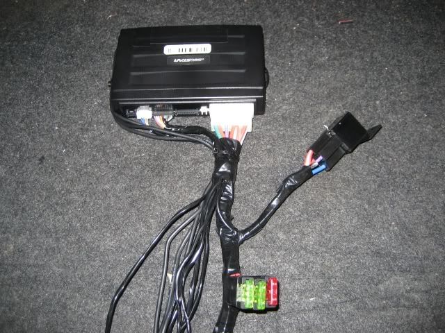
This is what My system looked like after I finished prepping it
Note: the extra relay on the side is for "Ignition 2"
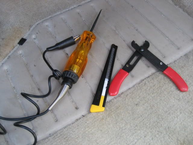
Here are the tools that you'll be using the most throughout the install:
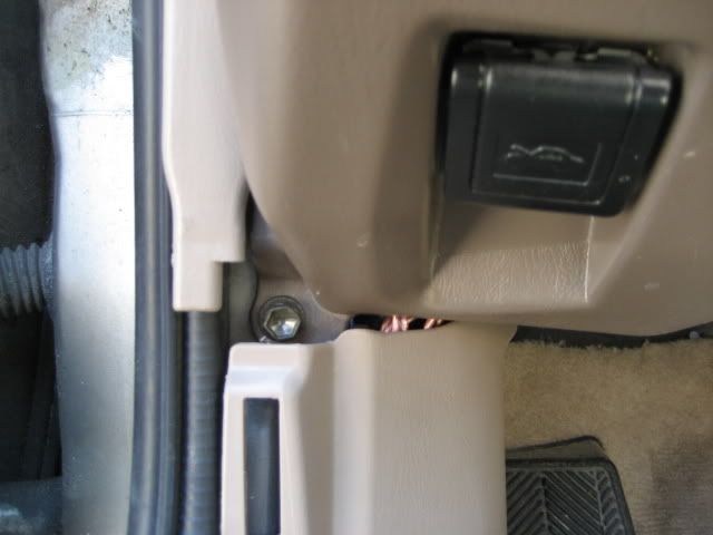
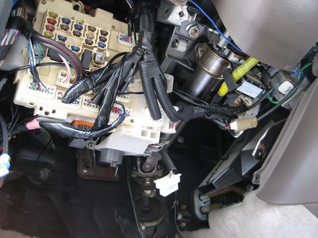
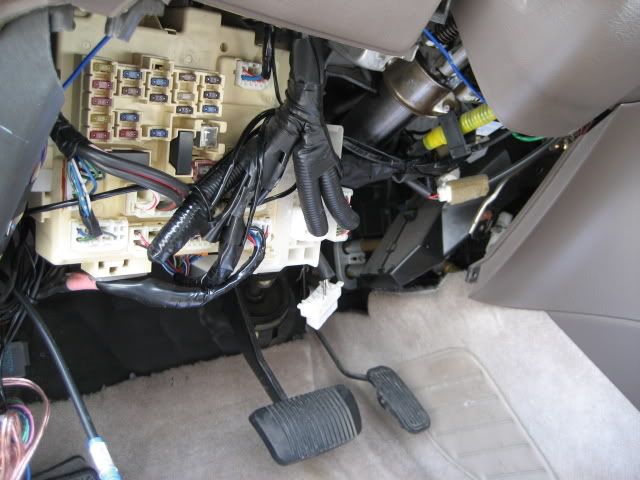
you are now ready to take your freshly prepped alarm to the car and begin the installation process. When you get to the car, you can start by removing the lower dash panel. There are several phillips screws holding it in, as well as one hidden 10mm bolt. You'll have to remove the kick panel and scuff plate to get to it. Pic is below.
Once you have the dash panel off, you'll also have to remove the metal one thats just behind it....there are four 10mm bolts holding it on (not shown).
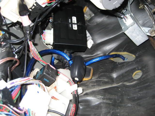
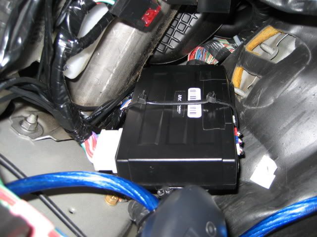
Once you have full access, you can begin by mounting the brain in a suitable place that is not going to interfere with any moving parts such as the gas, or brake pedals. You also dont want it anywhere near the steering collumn. Be creative with this becuase keep in mind that the better its hidden, the harder it'll be for someone to break in and rip it out. I put mine high under the dash as shown in the following pic.
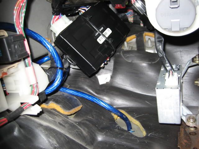
Notice that in the above pics, after I mounted the brain with zip ties, I roughly routed the wires close to where they will end up being connected.
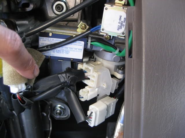
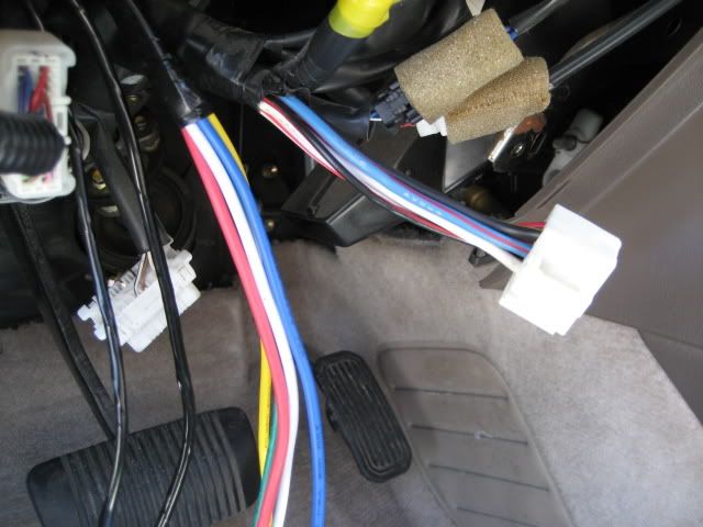
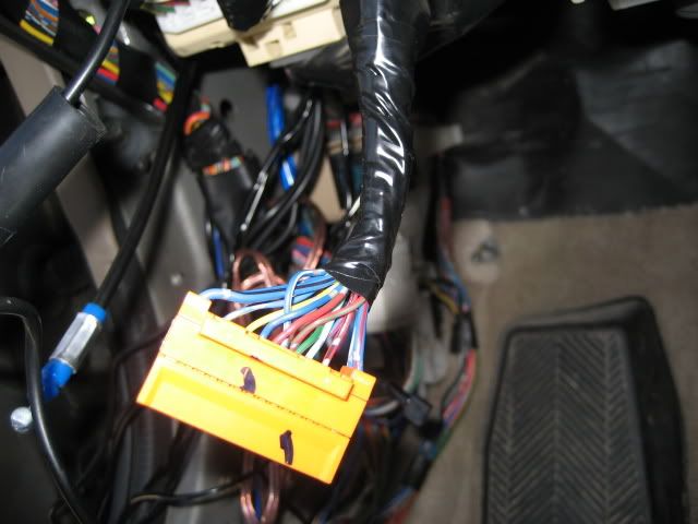
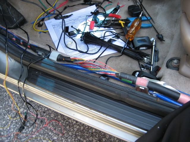
Your first wire connections are to be made at the key cylinder. You can access that harness from the position shown in the pic. I unplugged it in order to gain better access to them while making my connections. It is up to you to verify which colours do what BEFORE you unplug it and attach wires to them.
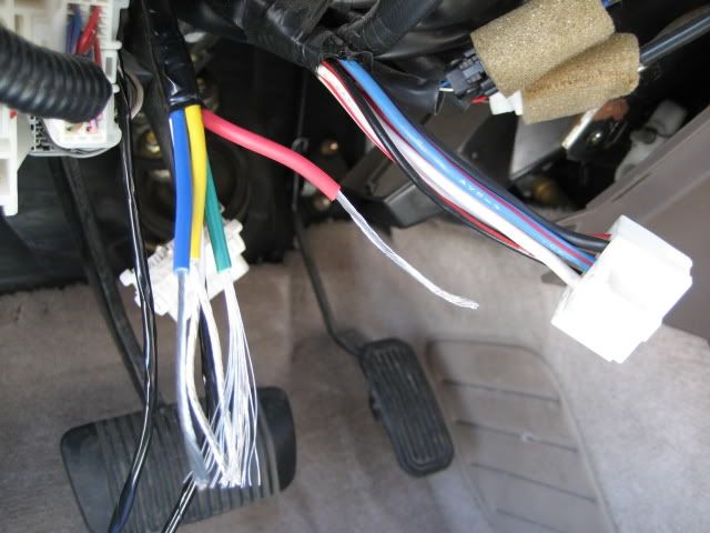
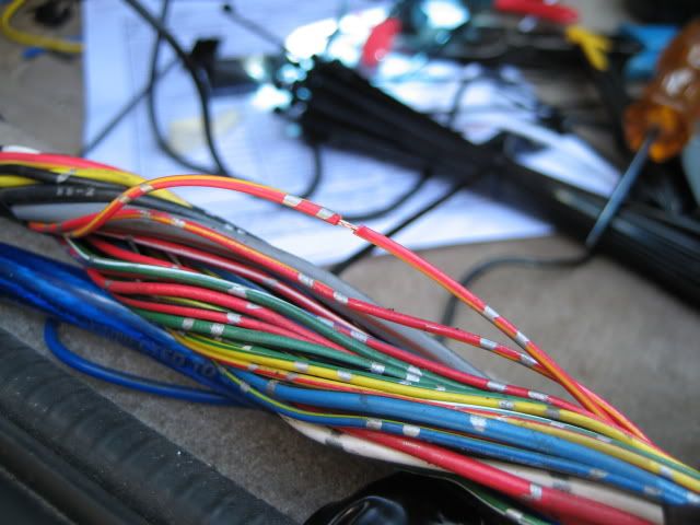
Peel all the ignition wires from the alarm (about 1.5 inches in length)
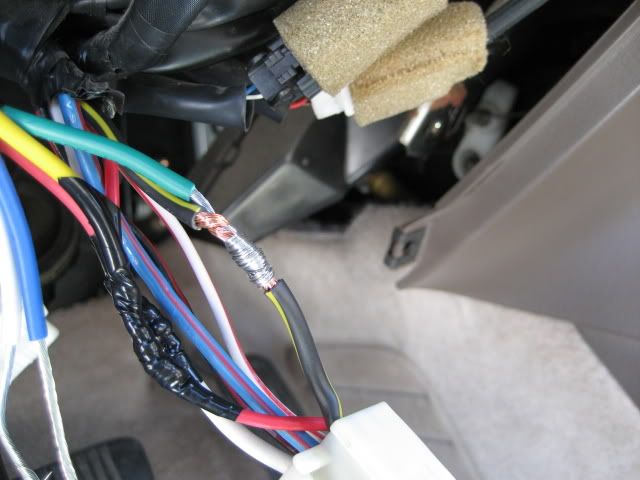
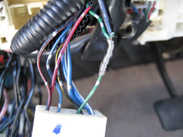
You are about to make your first connection to the car. Look closely at how I am doing it. This is the proper way to make a solid connection without the need for soldering. If you do ALL your connections the way I've done, then you'll have no need for messy soldering, and the connections will be tight and strong.
You'll start by connecting the main power wire from the alarm. Peel the WHITE wire (12volt constant) on the car just as I have.
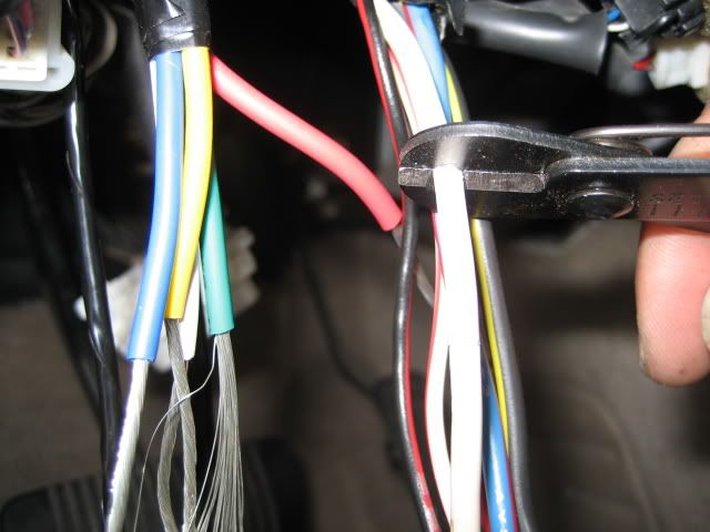
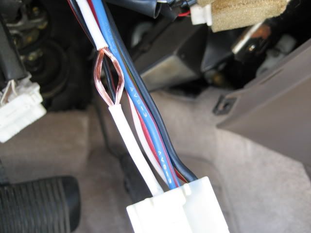
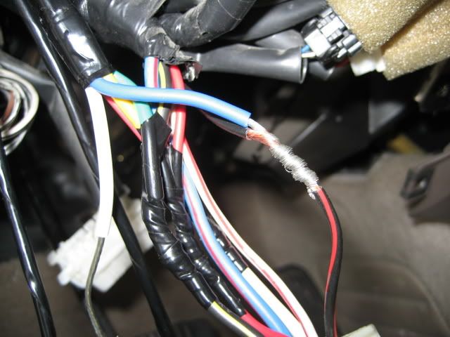
Notice that I actally removed a portion of the insulation on the wire, and then poked a hole through it. You're now going to take the power wire from the alarm (red in this case)...poke it through the "hole" in the wire that you made, and wrap the remaining wire around and around nice and tight.
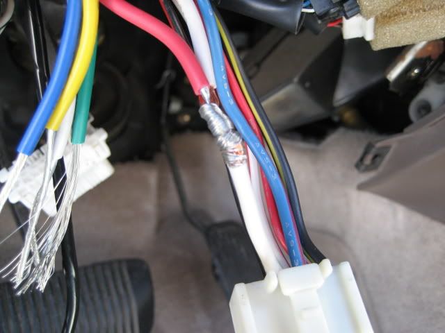
After you've made the wire connection, tape it up, again nice and tight. And don't be cheap on the tape. Make sure the connection is fully covered as I've done.
Next, you're gonna connect the Starter wire. In this case its a yellow wire from the alarm going to the Red wire on the car.
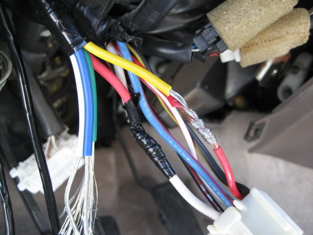
After the starter wire you're going to connect the Ignition 1 wire. In this case, its a green wire, connecting to a black/yellow wire on the car.
After the the ignition 1 wire, you're going to connect the Ignition 2 wire. In this case its going to be a blue wire, connecting to a black/red wire on the car.
After the ignition 2 wire, the final wire that you'll be connecting is the accessory wire. In this case it'd be a white wire going to a blue/red wire on the car. I opted NOT to make this connection because the only purpose of that blue/red wire is to turn the clock, and radio on in the car. I have no need for the radio to play when i remote start the car, so I didn't connect it. Note that the radio and clock will still be fully functional when the key is in the ignition.
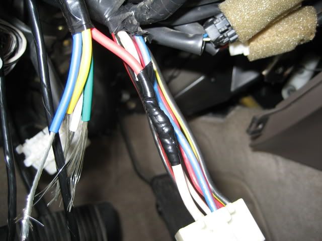
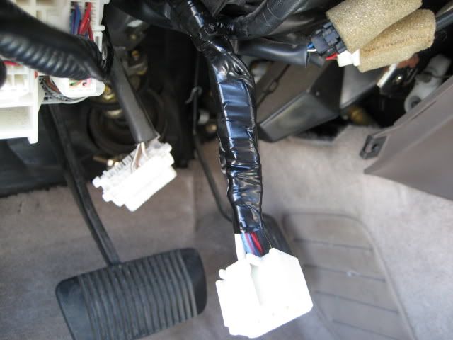
Double check all the connections you just made to make sure they're taped up properly....after that you can tape them all together as I have.
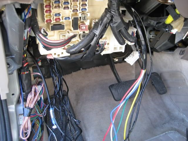
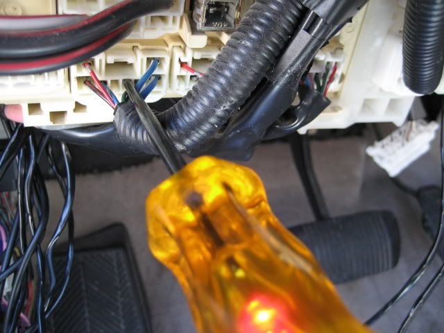
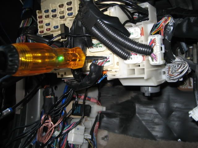
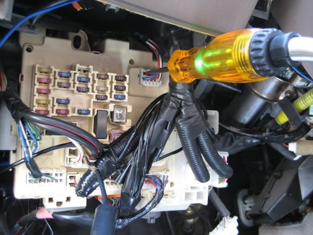
Your next connection is going to be made to the parking lights. The parking light wire is located on the bottom of the fuse box. I believe its the second harness from the left. The parking light wire is a smaller green wire. You can double check its authenticity as I have by using the test light. Since the test light lights up when i switch the parking lights on, I know its good. So I make the connection.
It's now time to ground the system. I ran my ground wire down into the kick panel and using a ring connector, I screwed it onto bare metal for a nice solid connection.
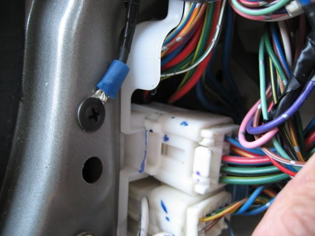
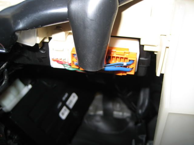
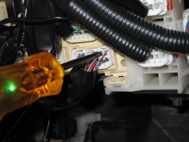
If you've made it this far, you're doing well. Now it's time to hook up the keyless entry portion of your alarm. On the car, you'll be looking for a dark blue, and dark blue/white. These wires are found at the very bottom of the fuse box in an orange connector. These wires also control the arming/disarming of the stock alarm.
After my connections were made, I taped the harness back up.
Your next connection is going to be to the brake switch. This wire on the car will have a 12volt pulse when your foot is on the brake. It's used to shut the remote starter down if someone tries to move the gear from the park position without the key.
This wire is green/white, and is found at the bottom of the fuse box. In my case, I connected the lightblue/white wire from the alarm to the brake wire on the car.
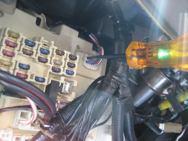
The next wire you'll connect is the door trigger wire. This is a wire that carries a ground pulse when any of the doors are opened. Its actually connected to the dome light, so you'll notice that even if the doors are closed, it'll still carry its power until the domelight fades away and turns off. This wire is red/white, and is found in a plug at the top-right corner of the fuse box. In my case, I was connecting a red/white wire, to the red/white door trigger wire on the car.
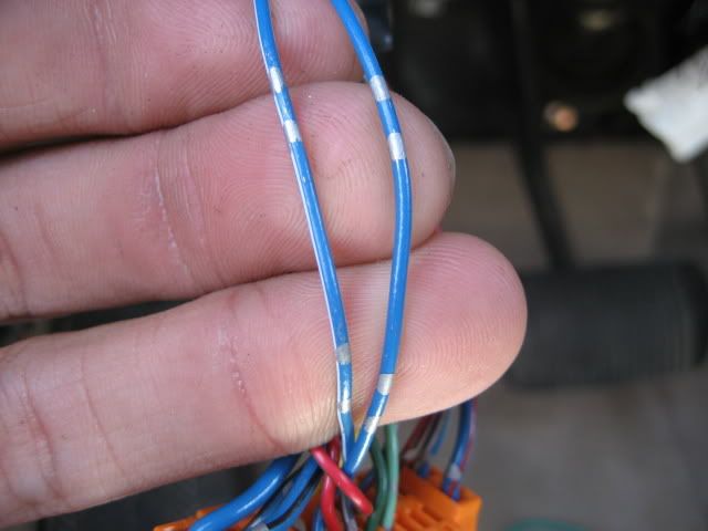
The trunk pin wire is next on the connections list. This wire carries a negative pulse when the trunk is popped open. It's used to trigger the alarm in the event that someone were to get into the trunk while the car is locked and armed. The wire is red/yellow in a wire harness running toward the rear of the car. You'll have to test this wire with the test light because there are TWO wires that are the same colour, but only ONE of them is the one you want. The wire you're looking for should only light the test light when the trunk is opened. In my case, I connected a purple/black wire from the alarm to the red/yellow trunk wire on the car.
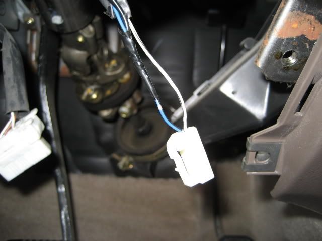
The FINAL connection that you'll make in the interior is at the key barrel again. Don't worry, the wire you need is NOT located in the huge harness you taped up at the beginning of the install. The wire you're looking for is the keysense wire. Its a blue/back wire located right near the key cylinder in a two-pin wire harness. You'll be connecting the "factory disarm" wire from the alarm to it. The purpose of this wire is to make sure that the stock alarm is not triggered when the car is remote started. If this connection is not made, then everytime you want to remote start the car, you'll have to unlock the car, remote start it, and then lock it back....all by yourself....which would be a pain in the ass IMO. In my case, I connected an orang/white wire from the alarm to a blue/black wire on the car.
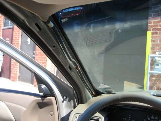
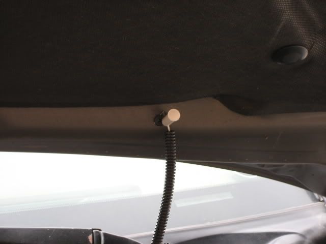
You're done the interior wiring portion of the install. The only thing left to run is the shock sensor, and the antenna. I put the antenna on the top-middle of the windshield for optimal range. Its easy to do. All you have to do it run the wire up A-pillar.
You have 3 connections to make under the hood of the car. You'll of course have to get those three wires from the interior of the car outside. Since this car was auto, I drilled a small hole through the clutch pedal plate, and ran them out that way. The wires I ran out were
1. Siren
2. Hood trigger
3. Tach.
Mount the siren using screws onto the firewall. I used a ring connector on the black wire, and grounded it right to the car. The red wire was connected to the siren output from the alarm (brown in my case).
For the hood trigger, the alarm comes with a pin switch which I never use because they're crap. They rust out, and stop working after only a couple months of use. Instead I used mercury switches that sense the position of the hood, and trigger the alarm.
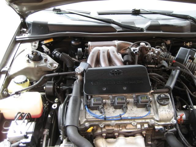
The tach wire Is very important. It is what senses that the engine in the car is running and tells the remote starter to stop cranking. The tach wire on the car is grey (V-6 models only). Its located at the igniter mounted on the driverside strut tower. In my case I connected a yellow/black wire from the alarm to the grey tach wire on the car.
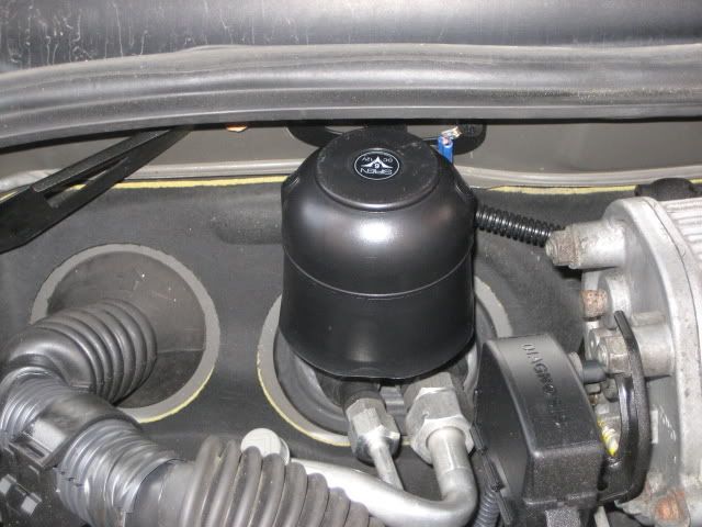
Mercury switch that I use:
This is what it looked like under the hood after I made all my connections. I use split loom to cover all the wires to protect them, and to make the install look cleaner.
This is what the install looked like in the interior when I was finished. The little "egg looking" thing you see is the shock sensor.
That concludes the installation process. There are a couple of side notes that I will bring forward now:
**This particular camry had a transponder key, and therefore required a self-learining module in order to remote start the car. I didn't mention that part of the install process because it would be very confusing to anyone trying this unless they used the exact same alarm with the exact same bypass module.
**This tutorial was made under the assumption that you know your way around your camry and you know where certain parts are, how to remove panels, etc.
**And last, but not least, I will mention again that I am NOT responsible for anyones car. You use this tutorial as a guide, and at your own risk.
At the end of the install, everything was tested, worked perfectly, and the car was returned to it's owner.
I can be reached through PM if you have any questions regarding this turorial or my methods of installation.
Nick
I keep coming across threads regarding alarm system installations, and it's always tough to help someone through it unless you're right there with them. So I decided to write this tutorial in the hopes of it being an effective tool/aid to those who are looking to undertake the daunting task of installing their own alarm/starter system.
Something to keep in mind: THIS TUTORIAL IS TO BE USED AS AN AID ONLY. SOME THINGS IN YOUR CAR MAY BE DIFFERENT, AND I AM NOT RESPONSIBLE FOR ANYONES MISTAKES. INSTALLING AN ALARM/STARTER IS NO EASY TASK FOR THE INEXPERIENCED. I do not recommend that anyone try this if you have no prior electrical experience. As an installer, I am using this to try and help. I can be reached through PM if anyone has any specific questions regarding the installation.
The install I'm about to walk you through was done on a 1999 TOYOTA CAMRY XLE AUTOMATIC. Although they are very similar to the gen1 solara, there will be slight differences....but for the most part, everything from this install can be applied directly to a gen1 solara. The system I installed was a Compustar Pro 2WFMAS.
So Let's Get Started.
1. The first thing you're gonna wanna do is prepare your system for install. Open the package and make sure everything is there. It makes for an easier install if you know exactly which wires you need to use on the alarm for any given vehicle. Typically you'll never use ALL the wires...so if you can eliminate the ones you know you wont need before you even get to the car, then it'll save you some trouble. Plus it'll make for a neater install. You'll know which wires to use based on whatever wiring diagram you're using as reference. I used this one:
http://64.85.6.121/diagrams/printpage.a ... 2&MakeID=2
You can see in the diagram, that you'll need the following wires:
12volt Constant - this is a wire that has power in it at all times regardless of the position of the key. It is what gives the alarm its power. (WHITE)
Ignition 1 - This is a wire that has power when the key is in the "on" position, and retains its power during cranking. (Black/yellow)
Ignition 2- This wire is the same as ignition 1, but these cars require that you power them BOTH up. Most remote starters will have another ignition output built in. (black/red).
Accessory - This is a wire that has power when the key is in the "ACC" , or "ON" position, but NOT the "crank" position. (Blue/red)
Starter - This wire only has power in it during crank. Its what sends the signal to the starter under the hood. (red)
Keysense - This is a wire that carries a ground when the key is in the ignition. This wire will be used to disarm the alarm system during remote starting. In doing this...the car will be able to remote start without the factory alarm going off. (blue/black)
Parking lights - This wire will carry a 12volt pulse when the parking lights are switched on. This wire will be used to flash the parking lights during arm/disarm, and remote start...it'll also flash the parking lights when the alarm is triggered. (green)
Power Lock - This wire has a ground pulse when the key is inserted in the passenger door, and turned to the "lock" position. It is used to lock all the doors, and arm the stock alarm. (darkblue/white)
Power Unlock - This wire has a ground pulse when the key is instered into the passenger door and turned to the "UNLOCK" position. It is used to unlock all the doors an to disarm the stock alarm. (darkblue)
Door trigger - This is a wire that has a ground pulse when any of the doors are opened. It is used to trigger the alarm system in the event that someone manages to open the door. (red/white)
Trunk trigger - This wire is used to trigger the alarm in the event that someone manages to open the trunk (red/yellow)
Brake Switch - This wire has a 12volt pulse when you put your foot on the brake pedal. It is used to shut the remote starter down in the event that someone gets into your car while its remote started. When they go to shift out of park...it'll shut down, and they wont get far. Its also used to cancel the remote starter if its no longer required by the user. (green/white)
TACH - This is an important wire to any remote start system. It carries an AC current when the engine is running. This is the wire that tells the remote starter when the engine is running so that remote starter stops cranking. Without this, the engine will continue to crank over even if the engine is running. (grey, V-6 models only)
Hood Trigger - This is a wire that is use to trigger the alarm in the event that the hood is opened. It's also used to cancel the remote start feature to prevent possible injury if someone is working under the hood.
Siren - This is a wire that comes from the brain and gives the siren (noise maker) the power to make its noises.
**After going through all of those wires on your particular alarm system, you can cut the rest of the remaining wires off, and tape them up since you will not need them. **
This is what My system looked like after I finished prepping it
Note: the extra relay on the side is for "Ignition 2"
Here are the tools that you'll be using the most throughout the install:
you are now ready to take your freshly prepped alarm to the car and begin the installation process. When you get to the car, you can start by removing the lower dash panel. There are several phillips screws holding it in, as well as one hidden 10mm bolt. You'll have to remove the kick panel and scuff plate to get to it. Pic is below.
Once you have the dash panel off, you'll also have to remove the metal one thats just behind it....there are four 10mm bolts holding it on (not shown).
Once you have full access, you can begin by mounting the brain in a suitable place that is not going to interfere with any moving parts such as the gas, or brake pedals. You also dont want it anywhere near the steering collumn. Be creative with this becuase keep in mind that the better its hidden, the harder it'll be for someone to break in and rip it out. I put mine high under the dash as shown in the following pic.
Notice that in the above pics, after I mounted the brain with zip ties, I roughly routed the wires close to where they will end up being connected.
Your first wire connections are to be made at the key cylinder. You can access that harness from the position shown in the pic. I unplugged it in order to gain better access to them while making my connections. It is up to you to verify which colours do what BEFORE you unplug it and attach wires to them.
Peel all the ignition wires from the alarm (about 1.5 inches in length)
You are about to make your first connection to the car. Look closely at how I am doing it. This is the proper way to make a solid connection without the need for soldering. If you do ALL your connections the way I've done, then you'll have no need for messy soldering, and the connections will be tight and strong.
You'll start by connecting the main power wire from the alarm. Peel the WHITE wire (12volt constant) on the car just as I have.
Notice that I actally removed a portion of the insulation on the wire, and then poked a hole through it. You're now going to take the power wire from the alarm (red in this case)...poke it through the "hole" in the wire that you made, and wrap the remaining wire around and around nice and tight.
After you've made the wire connection, tape it up, again nice and tight. And don't be cheap on the tape. Make sure the connection is fully covered as I've done.
Next, you're gonna connect the Starter wire. In this case its a yellow wire from the alarm going to the Red wire on the car.
After the starter wire you're going to connect the Ignition 1 wire. In this case, its a green wire, connecting to a black/yellow wire on the car.
After the the ignition 1 wire, you're going to connect the Ignition 2 wire. In this case its going to be a blue wire, connecting to a black/red wire on the car.
After the ignition 2 wire, the final wire that you'll be connecting is the accessory wire. In this case it'd be a white wire going to a blue/red wire on the car. I opted NOT to make this connection because the only purpose of that blue/red wire is to turn the clock, and radio on in the car. I have no need for the radio to play when i remote start the car, so I didn't connect it. Note that the radio and clock will still be fully functional when the key is in the ignition.
Double check all the connections you just made to make sure they're taped up properly....after that you can tape them all together as I have.
Your next connection is going to be made to the parking lights. The parking light wire is located on the bottom of the fuse box. I believe its the second harness from the left. The parking light wire is a smaller green wire. You can double check its authenticity as I have by using the test light. Since the test light lights up when i switch the parking lights on, I know its good. So I make the connection.
It's now time to ground the system. I ran my ground wire down into the kick panel and using a ring connector, I screwed it onto bare metal for a nice solid connection.
If you've made it this far, you're doing well. Now it's time to hook up the keyless entry portion of your alarm. On the car, you'll be looking for a dark blue, and dark blue/white. These wires are found at the very bottom of the fuse box in an orange connector. These wires also control the arming/disarming of the stock alarm.
After my connections were made, I taped the harness back up.
Your next connection is going to be to the brake switch. This wire on the car will have a 12volt pulse when your foot is on the brake. It's used to shut the remote starter down if someone tries to move the gear from the park position without the key.
This wire is green/white, and is found at the bottom of the fuse box. In my case, I connected the lightblue/white wire from the alarm to the brake wire on the car.
The next wire you'll connect is the door trigger wire. This is a wire that carries a ground pulse when any of the doors are opened. Its actually connected to the dome light, so you'll notice that even if the doors are closed, it'll still carry its power until the domelight fades away and turns off. This wire is red/white, and is found in a plug at the top-right corner of the fuse box. In my case, I was connecting a red/white wire, to the red/white door trigger wire on the car.
The trunk pin wire is next on the connections list. This wire carries a negative pulse when the trunk is popped open. It's used to trigger the alarm in the event that someone were to get into the trunk while the car is locked and armed. The wire is red/yellow in a wire harness running toward the rear of the car. You'll have to test this wire with the test light because there are TWO wires that are the same colour, but only ONE of them is the one you want. The wire you're looking for should only light the test light when the trunk is opened. In my case, I connected a purple/black wire from the alarm to the red/yellow trunk wire on the car.
The FINAL connection that you'll make in the interior is at the key barrel again. Don't worry, the wire you need is NOT located in the huge harness you taped up at the beginning of the install. The wire you're looking for is the keysense wire. Its a blue/back wire located right near the key cylinder in a two-pin wire harness. You'll be connecting the "factory disarm" wire from the alarm to it. The purpose of this wire is to make sure that the stock alarm is not triggered when the car is remote started. If this connection is not made, then everytime you want to remote start the car, you'll have to unlock the car, remote start it, and then lock it back....all by yourself....which would be a pain in the ass IMO. In my case, I connected an orang/white wire from the alarm to a blue/black wire on the car.
You're done the interior wiring portion of the install. The only thing left to run is the shock sensor, and the antenna. I put the antenna on the top-middle of the windshield for optimal range. Its easy to do. All you have to do it run the wire up A-pillar.
You have 3 connections to make under the hood of the car. You'll of course have to get those three wires from the interior of the car outside. Since this car was auto, I drilled a small hole through the clutch pedal plate, and ran them out that way. The wires I ran out were
1. Siren
2. Hood trigger
3. Tach.
Mount the siren using screws onto the firewall. I used a ring connector on the black wire, and grounded it right to the car. The red wire was connected to the siren output from the alarm (brown in my case).
For the hood trigger, the alarm comes with a pin switch which I never use because they're crap. They rust out, and stop working after only a couple months of use. Instead I used mercury switches that sense the position of the hood, and trigger the alarm.
The tach wire Is very important. It is what senses that the engine in the car is running and tells the remote starter to stop cranking. The tach wire on the car is grey (V-6 models only). Its located at the igniter mounted on the driverside strut tower. In my case I connected a yellow/black wire from the alarm to the grey tach wire on the car.
Mercury switch that I use:
This is what it looked like under the hood after I made all my connections. I use split loom to cover all the wires to protect them, and to make the install look cleaner.
This is what the install looked like in the interior when I was finished. The little "egg looking" thing you see is the shock sensor.
That concludes the installation process. There are a couple of side notes that I will bring forward now:
**This particular camry had a transponder key, and therefore required a self-learining module in order to remote start the car. I didn't mention that part of the install process because it would be very confusing to anyone trying this unless they used the exact same alarm with the exact same bypass module.
**This tutorial was made under the assumption that you know your way around your camry and you know where certain parts are, how to remove panels, etc.
**And last, but not least, I will mention again that I am NOT responsible for anyones car. You use this tutorial as a guide, and at your own risk.
At the end of the install, everything was tested, worked perfectly, and the car was returned to it's owner.
I can be reached through PM if you have any questions regarding this turorial or my methods of installation.
Nick
Last edited by TLMNICK on Wed Apr 29, 2009 6:05 pm, edited 1 time in total.

-

TLMNICK - SolaraGuy Driver

- Posts: 838
- Joined: Sun Jul 20, 2008 10:36 am
- Location: Toronto