[phpBB Debug] PHP Notice: in file /viewtopic.php on line 988: date(): It is not safe to rely on the system's timezone settings. You are *required* to use the date.timezone setting or the date_default_timezone_set() function. In case you used any of those methods and you are still getting this warning, you most likely misspelled the timezone identifier. We selected 'Europe/Moscow' for 'MSD/4.0/DST' instead
[phpBB Debug] PHP Notice: in file /viewtopic.php on line 988: getdate(): It is not safe to rely on the system's timezone settings. You are *required* to use the date.timezone setting or the date_default_timezone_set() function. In case you used any of those methods and you are still getting this warning, you most likely misspelled the timezone identifier. We selected 'Europe/Moscow' for 'MSD/4.0/DST' instead
SolaraGuy.com • View topic - hack my ride
Talk about aftermarket Toyota Solara Gen 1-1.5 upgrades.

hack my ride

Postby Dawgz » Mon Sep 28, 2009 9:06 pm

Gibson99 wrote:
Eye8Pussies wrote:let us know how it goes....I'm too lazy to ask my electrical eng friends to help me out. if you can figure everything out, it'd make it easier...lol


so far so good. i expected my CEL to come back on, and it did. but that's because my EGR system is blocked off. but right now that's the only code, and catalyst monitoring shows COMPLETE! i'm gonna drive it this way for the rest of the week and read the codes again and make sure that EGR is the only code i have, and if so, i'm gonna go ahead and solder it all up and mount it in the dash!

before anyone asks, NO i do not plan to sell these or even sell kits. like i said, i'm only marginal at soldering, and i don't want to deal with returns on something little like this. you really can buy all the parts at radio shack for about $15 and DIY. click the link in my first post - that's the plan i'm following. i did use different LEDs but they are within 0.1 volt and have the same mA rating, so it's close enough. there IS a little wiggle room in the design. one thing they don't tell you is that the capacitors need to be electrolytic (the only kind that have a polarity), and they need to be 35v not 50v (50's seem to be more common). i couldn't find 35v el.caps at fry's, but resistors and leds are way cheaper at fry's. besides, radio shack seems to be phasing out the electrical components section of the store. they used to take up the entire back of the store. now you're lucky if they have 10 small drawers full of parts. maybe that's why they're renaming themselves "The Shack".

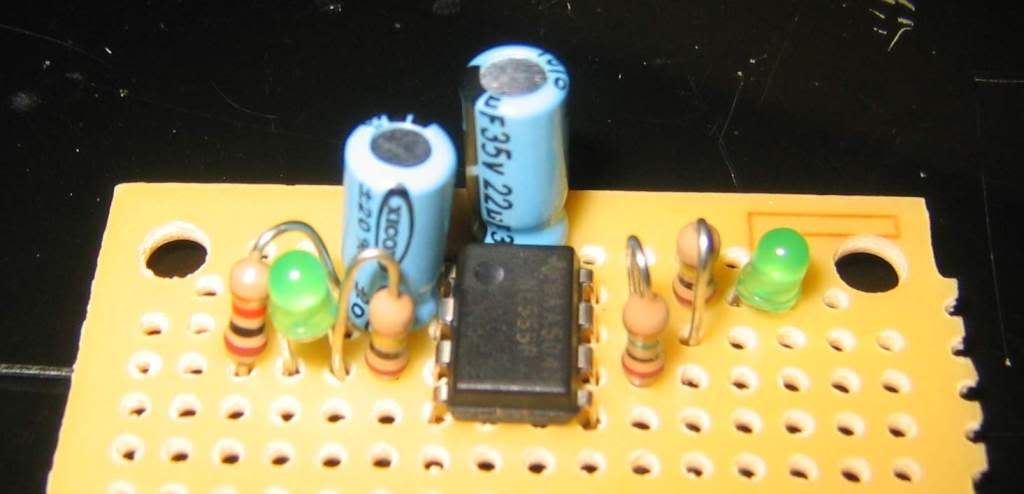
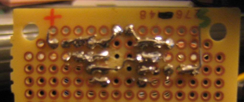
now i CAN take detailed pictures of my pcb once i'm done so you can see a good way to lay out the parts - that was the hardest part for me - figuring out ways to route components without using jumper wires. turns out there's no other way to bridge 2 of the pins on the chip, so i had to use a jumper - you can see the gray wire going over the black chip in the center.

so i guess that means i need to figure out how to use macro mode on my camera...


If u can put up a diagram and a pic of ur setup, I can make a compact setup for anyone who wants it.
--=Black on Black=-- (Sold)
User avatar
Dawgz
SolaraGuy Professional Racer
 
Posts: 4678
Joined: Fri Jul 16, 2004 2:28 pm

Postby Gibson99 » Mon Sep 28, 2009 9:19 pm

schematic is available on the mkiv link in first post ("what i'm up to")

once i get it all laid out on the board i can take pics of both sides, label parts, and post the pics.

the board they specify in the mkiv link is actually already pretty small, though you could even cut it in half (after breaking apart the 2 pieces) and still have plenty of room to work. i may do this as well to make it even more compact.
User avatar
Gibson99
SolaraGuy Driver
SolaraGuy Driver
 
Posts: 350
Joined: Mon Feb 09, 2009 3:09 pm
Location: Cypress, TX

Postby Gibson99 » Sat Oct 03, 2009 8:01 pm

ok! so far so good. i'm gonna call this one DONE! well, it works on a breadboard anyway. now i just need to solder it up on a real circuitboard to make it permanent and mount it.

next step to do this 100% is to find a resistor that matches the impedance (ohms) and current draw (amps) of the heating element in the oxygen sensor, so i can completely eliminate the sensor. but since the o2 sensor is still there and still hooked up, i don't HAVE to do this.
User avatar
Gibson99
SolaraGuy Driver
SolaraGuy Driver
 
Posts: 350
Joined: Mon Feb 09, 2009 3:09 pm
Location: Cypress, TX

Postby TxBmbleBee » Sat Oct 03, 2009 8:18 pm

amazing. so i would not have to run a cat with this resistor in place?
"i just wanna go fast..."
TxBmbleBee
SolaraGuy Driver
SolaraGuy Driver
 
Posts: 751
Joined: Mon Jan 05, 2009 4:52 pm

Postby Gibson99 » Sun Oct 04, 2009 9:40 pm

no cat required. that's the whole point. but this is significantly more than just a resistor. just look:

front of board
Image

backside:
Image

yeah, my soldering skills leave a lot to be desired, but it gets the job done. i cut the board off leaving one row of empty holes below the actual circuit, so the board in my car now is about 1.5" wide and 0.5" long, and the components are 0.5" tall. i put some self-stick foam on the back to help insulate the solder side, and zip-tied it to the vehicle harness using one of the big holes in the corner of the board.

i think i'm done with this for now. i still have the o2 sensor installed so that it won't throw an o2 sensor heater circuit code, but if i ever change my exhaust, the o2 sensor will stay in the greddy piping (can't easily be removed) and i'll have to come up with a resistor to match the heating element in the o2 sensor. but that's down the road.
User avatar
Gibson99
SolaraGuy Driver
SolaraGuy Driver
 
Posts: 350
Joined: Mon Feb 09, 2009 3:09 pm
Location: Cypress, TX

Postby JamesT » Sun Oct 04, 2009 9:50 pm

Nice work!

I'm still working on the EGR black box thing - you've given me some motivation here!
Image
Click on picture for my CarDomain
BespokeAutoInterior
User avatar
JamesT
Shift Boot Master Crafter
 
Posts: 556
Joined: Wed Aug 20, 2008 6:47 pm
Location: Chicago

Postby Gibson99 » Mon Oct 05, 2009 6:34 am

well i'll admit that i did no real research here. the LEDs i used were from frys and cost way less than the ones from radio shack but were close enough in terms of current draw and voltage drop. i AM learning more about electronics though! i couldn't look at a resistor and tell you its value based on the color bands without looking at a chart, but at least i can tell how it should be installed and whatnot.

i'm planning on getting my egr system repaired and making it functional again. not sure if i'll have a flex section in my new upper pipe, but time will tell. hopefully i'll have time to meet up with my welder buddy this week.
User avatar
Gibson99
SolaraGuy Driver
SolaraGuy Driver
 
Posts: 350
Joined: Mon Feb 09, 2009 3:09 pm
Location: Cypress, TX
Previous

Return to Aftermarket Gen1 and 1.5

Who is online

Users browsing this forum: No registered users and 11 guests